Influence of stiffness on force distribution
- kamilmaruszakuk
- Apr 29, 2018
- 2 min read
Updated: Oct 8, 2020
A static analysis of a structure gives a connection design engineer the forces acting on a given connection. The next step is to distribute the internal forces onto each part of the joint. It is not always possible to determine the real distribution of forces in the connection. It may be defined in a rational and realistic way and this is one of the most difficult parts of the connection design process, requiring that the engineer have a good understanding of the structural behaviour of connections. The assumed distribution of forces must satisfy the following conditions: all internal forces must be in equilibrium with the applied forces; each part of the connection must resist the forces assumed in the analysis; each part of the connection must have sufficient deformation capacity.
There are some rules which help with understanding the behaviour of joints. One of the most important deals with the stiffness of the various parts in a connection. Stiffer elements attract more loads than flexible elements. This principle can be easily shown in the following example.
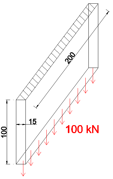
Let us consider a cantilever plate with the dimensions shown in Figure 1 and with a vertical load of 100kN applied on its end.

Figure 1.
The deflection of the plate is:

The same plate loaded with an in-plane load, see Figure 2, gives us the following displacement:


Figure 2.
If we now connect two plates together, see Figure 3, both displacements at the interface are then equal and the load is shared in proportion to the stiffness ratio of the two elements.

Figure 3.
Stiffness ratio: 2.822mm/0.0159mm=177.5 [-];
Reaction R1= 100kN/177.5=0.56 kN;
Reaction R2=100kN-0.56kN = 99.44 kN.
As a result, almost the whole load is taken by the vertical plate loaded in tension.
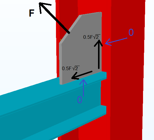
Another example might be the brace connection between the beam flange and the column web, see Figure 4.

Figure 4.
For simplicity, it is assumed that, for whatever reason, a gusset plate is not centred with the beam web. The bracing force F will cause bending of the beam flange (beam side) and also bending of the column web (column side). These deformations from the tensile components are bigger than the deformations from the shear components. It can be assumed then that the force is transferred only through shear.
A similar situation occurs in Figure 5 in a connection between a plate and a box column. The deformations from the shear are much smaller than the deformations from the tensile components that are causing bending of the section walls. The correct force distribution is where the welds are only in shear.

Figure 5.
It can therefore be concluded that if there are two possible types of load transfer, the load transfer with larger deformations may sometimes be ignored and it can be assumed that the whole load is transferred to the element that gives the smaller deformations.


